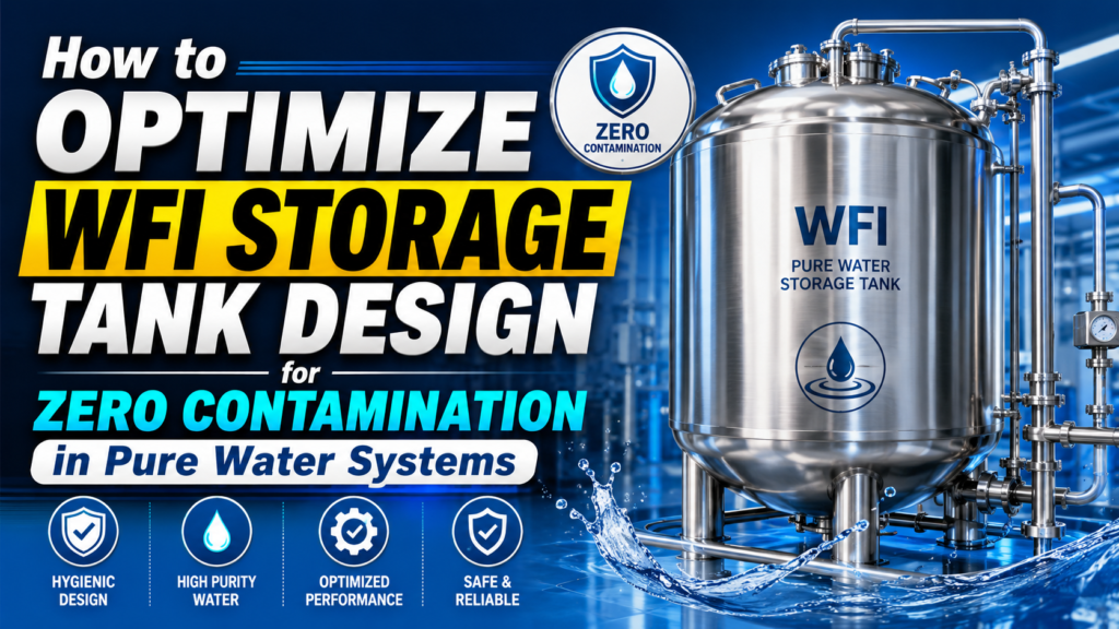
Water for Injection sits at the very foundation of sterile pharmaceutical manufacturing. It is used to formulate parenteral products, to rinse product-contact equipment, and to prepare cleaning solutions across the plant — which means that if the WFI storage tank manufacturers system itself becomes a source of microbial or endotoxin contamination, the effect cascades through every downstream process that touches it. For engineers managing high-purity water loops, the storage tank is frequently the weakest link in an otherwise well-controlled system, simply because it holds water in a relatively static state for extended periods, giving any contamination that does occur time to establish and multiply.
This article looks at the structural and process design choices that separate a genuinely contamination-resistant WFI storage tank from one that merely looks the part on a datasheet, and what engineers should be verifying when evaluating WFI storage tank manufacturers.
The Critical Role of Water for Injection Storage in Pharma
Unlike purified water, WFI must meet significantly tighter limits on bacterial endotoxins, and both the European Pharmacopoeia and USP specify strict conductivity,
total organic carbon, and microbial limits that must be maintained not just at the point of generation but throughout storage and distribution. WFI is typically stored and circulated at elevated temperature — commonly above 80°C — specifically because this temperature range is inhospitable to bacterial growth,
turning the storage tank itself into an active control point rather than a passive holding vessel.
This changes the entire engineering brief. A WFI tank is not simply a container; it is a piece of process equipment that must maintain temperature uniformity,
prevent any zone of stagnant or cooled water from forming, and integrate seamlessly with a continuously circulating distribution loop that returns water to the tank after passing through use points across the facility.
Structural Safeguards Against Microbial Growth
Every structural decision in a WFI tank design traces back to one goal: eliminating any surface, geometry, or fitting where water can sit still, cool down, or accumulate biofilm. This starts with the tank’s internal geometry — a dished or conical bottom is standard, ensuring complete gravity drainage with no low points where residual water can pool after a drain-down cycle.
Internal fittings are kept to an absolute minimum, and where instrumentation such as level sensors or temperature probes must penetrate the vessel,
they are specified as flush-mounted, non-invasive designs rather than dip-tube style fittings that would otherwise create a stagnant internal volume.
Orbital Welding and Mechanical Passivation Requirements
Manual TIG welding, however skilled the welder, introduces variability into weld bead geometry and heat input that can leave micro-irregularities on the interior surface of a pipe or vessel nozzle. Orbital welding — an automated process where a rotating welding head moves around the pipe under precisely controlled parameters — produces a consistent, smooth,
fully penetrated weld with minimal internal weld bead protrusion, every single time. For WFI systems,
orbital welding of all product-contact piping and vessel connections is considered standard practice rather than a premium option,
since the alternative introduces exactly the kind of surface irregularity that undermines the entire contamination-control strategy.
Following fabrication, mechanical passivation — typically a citric acid bath treatment — removes free iron contamination left behind by fabrication tools and welding, restoring and strengthening the passive chromium-oxide layer on the stainless steel surface. This step should never be skipped,
and procurement teams should request the passivation certificate as a standard deliverable alongside the mill test certificate.
Implementing 0.2 µm Vent Filters and Nitrogen Blanketing Systems
As WFI is drawn from or added to the tank, air must move in or out to equalize pressure. That air pathway is a direct route for airborne microbial contamination unless it is properly filtered. A hydrophobic 0.2 µm rated vent filter is the standard control here,
sized to accommodate the tank’s maximum fill and draw-down flow rates without creating excessive pressure differential across the filter membrane,
which can otherwise cause tank deformation on large-volume systems.
Some facilities go a step further and implement nitrogen blanketing,
maintaining a slight positive pressure of inert nitrogen gas above the water surface. This further reduces the risk of oxidation and displaces oxygen that could otherwise support aerobic microbial growth in any residual headspace moisture. Nitrogen blanketing adds complexity and cost,
and is generally reserved for larger biotech production facilities or products with particularly stringent bioburden requirements, but it is worth evaluating during the design phase rather than retrofitting later.
Sizing and Capacity Scaling: From 500L to 50,000L Systems
WFI tank sizing is rarely a simple function of daily consumption volume. Engineers need to account for peak demand periods, generation system output rate,
and the buffer capacity needed to avoid production downtime if the WFI generation skid requires unscheduled maintenance. A common design approach targets a minimum buffer of one to two days of average consumption,
though this varies considerably based on the criticality of the downstream processes served.
Smaller biotech and clinical-batch facilities frequently operate in the 500L to 2,000L range, where a single small-diameter tank with a compact circulation loop is sufficient. Larger commercial-scale API and formulation facilities routinely specify 10,000L to 50,000L systems,
at which point tank geometry, structural support, seismic considerations (in applicable regions), and the pump sizing for the return loop all become significantly more involved engineering exercises. At every scale,
the underlying design principles — complete drainability, minimal dead legs, continuous circulation,
and elevated storage temperature — remain constant; only the mechanical execution changes.
Meeting EP, USP, and WHO-GMP Guidelines for Purified Water
Regulatory expectations for WFI systems are well documented but require careful interpretation at the equipment specification stage. The European Pharmacopoeia’s monograph on Water for Injection,
USP’s parallel chapter, and WHO’s guidance on pharmaceutical water systems all converge on the same core principles: continuous circulation,
validated storage temperature, regular microbial and endotoxin monitoring,
and a fully documented qualification package covering design, installation, operational,
and performance qualification (DQ/IQ/OQ/PQ).
Procurement teams evaluating tank manufacturers should confirm the vendor’s familiarity with generating a validation-ready documentation package aligned to these frameworks from the outset,
rather than treating compliance as an afterthought layered on top of a generic tank design. A fabricator experienced in pharmaceutical water systems will typically have standard qualification protocol templates already developed,
which meaningfully shortens the commissioning timeline on a new facility build-out.
Instrumentation and Monitoring for Ongoing System Integrity
A well-designed WFI storage tank is only half the contamination-control equation; ongoing monitoring confirms that the design intent is actually being achieved in daily operation. Continuous conductivity monitoring at multiple points in the distribution loop,
along with periodic total organic carbon (TOC) testing,
provides real-time indication of chemical purity drift that could signal a system integrity issue before it becomes a microbiological problem. Temperature monitoring throughout the circulation loop,
not just at the tank itself,
confirms that no section of the distribution piping is falling below the validated minimum temperature that keeps microbial growth suppressed.
Online microbial monitoring technologies have advanced considerably and are increasingly specified alongside traditional offline plate-count testing,
offering faster detection of any bioburden excursion than the multi-day incubation period traditional methods require. Engineers designing a new WFI system should evaluate at the outset which combination of online and offline monitoring will be integrated,
since retrofitting monitoring instrumentation into an already-installed tank and loop is considerably more disruptive than specifying sensor ports and sampling points during the original design phase.
Facilities should also build a documented response protocol for any monitoring excursion,
defining the investigation, containment, and requalification steps that follow a detected deviation,
since regulatory inspectors consistently expect to see that a facility’s monitoring programme is backed by a functioning response process,
not simply a stream of data that is collected but not meaningfully acted upon.
Frequently Asked Questions
Why is WFI stored hot rather than at ambient temperature? Storing and circulating WFI above 80°C creates conditions that are inhospitable to most bacterial growth,
turning storage temperature itself into an active contamination-control mechanism rather than relying solely on periodic sanitization of an ambient-temperature system.
What is the difference between WFI and purified water storage tank requirements? Purified water systems generally permit ambient temperature storage with periodic ozonation or UV sanitization,
while WFI systems require continuous circulation at elevated temperature,
tighter microbial and endotoxin limits,
and generally more stringent dead-leg and surface finish requirements throughout the storage and distribution loop.
How is tank temperature uniformity verified during qualification? Temperature mapping studies, using multiple calibrated temperature sensors placed at various points within the tank and distribution loop during performance qualification,
confirm that no zone falls outside the validated temperature range under both static storage and active circulation conditions.
Does nitrogen blanketing require continuous nitrogen supply infrastructure? Yes — nitrogen blanketing requires a dedicated nitrogen supply line with pressure regulation and a backup supply strategy,
since any interruption in nitrogen supply during operation can allow air ingress into the tank headspace,
undermining the contamination-control benefit the system was installed to provide.
Buyers comparing specifications across vendors can review WFI storage tank manufactured in SS 316L listings to benchmark construction standards and documentation packages before shortlisting suppliers for a formal quotation.