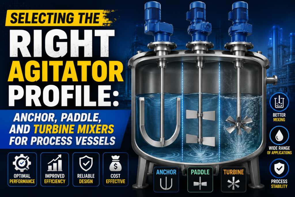
Choosing an agitator is one of those specification decisions that looks simple on paper and turns out to have outsized consequences on process outcomes. Get the impeller profile wrong for the fluid you’re mixing, and you end up with dead zones, inconsistent product quality, or a motor that’s either badly underpowered or needlessly oversized. This guide walks through how to match agitator geometry to process fluid behaviour on an industrial jacketed agitator vessel, along with the sealing and pressure-rating decisions that go alongside it.
Why Fluid Viscosity Dictates Your Agitator Mechanical Design
Viscosity is the starting point for nearly every agitator selection decision, because it directly determines the flow regime the impeller will be operating in. Low-viscosity fluids, similar to water,
mix easily under turbulent flow conditions generated by relatively small, fast-turning impellers. As viscosity climbs — into the range of syrups, slurries,
or polymer solutions — flow becomes increasingly laminar near the vessel wall, and a fast,
small-diameter impeller simply cannot move that fluid effectively; it ends up carving a localized vortex around itself while the bulk of the vessel content remains essentially unmixed.
This is why impeller selection cannot be treated as a generic checkbox on a vessel specification. Operations heads need to supply actual process viscosity data — ideally across the full range the product will exhibit during a batch, since many formulations change viscosity substantially as they heat, cool,
or react — to any fabricator or process engineer designing the agitation system.
Anchor Profiles vs. Turbine Impellers: High Viscosity vs. High Shear
Anchor agitators are designed with blades that closely follow the internal contour of the vessel wall, typically with a small clearance gap measured in millimetres. This geometry makes them exceptionally effective for high-viscosity fluids, since the anchor continuously scrapes product away from the heated or cooled vessel wall,
preventing the formation of an insulating stagnant layer that would otherwise severely degrade heat transfer efficiency — a particularly important consideration on any jacketed vessel where thermal performance is part of the process goal. Anchors generate primarily tangential flow at relatively low rotational speed,
making them well suited to viscous pastes, creams, and slurries,
but poorly suited to applications requiring fine particle dispersion or rapid blending of low-viscosity liquids.
Turbine impellers sit at the opposite end of the spectrum. Radial-flow turbines (such as flat-blade disc turbines) and axial-flow turbines (such as pitched-blade or hydrofoil designs) operate at significantly higher rotational speeds and generate strong shear forces concentrated near the impeller itself. This makes turbines the clear choice for applications requiring emulsification, gas dispersion, rapid dissolution of solids,
or fine particle size reduction. However, turbines lose effectiveness rapidly as viscosity increases, since their comparatively small blade diameter cannot project sufficient flow to move a viscous fluid through the full vessel volume.
For process fluids that shift significantly in viscosity across a batch cycle — starting thin and thickening as a reaction proceeds, for example — some vessel designs incorporate dual or combination agitators,
mounting both an anchor and a smaller high-speed turbine on a common or independently driven shaft, giving operators the flexibility to switch or combine mixing modes as the batch progresses.
Mechanical Sealing: Top-Entry vs. Bottom-Entry Configuration Safety
Where the agitator shaft penetrates the vessel matters as much as the impeller geometry itself,
particularly from a safety and containment standpoint. Top-entry configurations, where the motor and gearbox sit above the vessel and the shaft descends through the top head,
are the most common arrangement and generally offer easier maintenance access, since the seal and gearbox assembly can often be serviced without fully draining or opening the vessel.
Bottom-entry configurations mount the drive assembly beneath the vessel, with the shaft entering through the bottom head. This arrangement is sometimes preferred for very tall,
narrow vessels where a long top-entry shaft would be prone to excessive deflection or vibration, but it introduces a more critical containment consideration: any seal failure at a bottom entry point creates a direct leak path for the full hydrostatic head of product in the vessel, rather than the comparatively lower-consequence leak of a top-entry seal failure. For hazardous, toxic,
or high-value process fluids, this risk differential is significant enough that most engineering teams default to top-entry designs unless there is a compelling process reason to do otherwise.
Seal type itself — packed gland, single mechanical seal, or double mechanical seal with barrier fluid — should be specified based on the fluid’s hazard classification and the acceptable leakage tolerance,
with double mechanical seals generally mandated for any process handling flammable, toxic, or environmentally regulated substances.
Operating Under Pressure: The Necessity of Full Vacuum Ratings
Many chemical processes involve vacuum operation at some stage — vacuum distillation, degassing, or drying — and an agitator system that was design only for atmospheric operation can fail catastrophically under vacuum conditions if the shaft seal, gearbox, or vessel structure were not rate accordingly. A full vacuum rating means the vessel and its agitator assembly are engineer to withstand a complete vacuum (approaching -1 bar gauge) without structural deformation, seal failure,
or air ingress that would compromise process integrity.
Specifying full vacuum capability upfront, even for processes that only occasionally operate under vacuum, is generally more cost-effective than retrofitting a vessel later, since vacuum rating affects fundamental structural decisions including wall thickness, head design,
and stiffening ring placement that are far more difficult and expensive to modify after fabrication than to specify correctly the first time.
Vetting Manufacturer Machining Tolerances Online
Agitator performance is only as good as the mechanical precision behind it — shaft straightness, bearing housing alignment, and impeller balance all directly affect vibration levels, seal life,
and long-term maintenance cost. When evaluating fabricators through an online process equipment marketplace India buyers increasingly rely on,
it’s worth specifically requesting documented machining tolerance data and dynamic balancing certificates for the agitator shaft assembly,
rather than relying solely on the general reputation of the manufacturer.
Baffle Design and Its Interaction with Agitator Performance
Impeller selection does not operate in isolation from the vessel’s internal geometry,
and baffle design is one of the most consequential — and most frequently overlooked — factors affecting actual mixing performance. In an unbaffled vessel, especially with a centrally mounted turbine impeller running at higher speed, the bulk fluid tends to rotate as a single mass around the shaft rather than mixing thoroughly,
a phenomenon known as vortexing, which severely limits actual mixing effectiveness regardless of how well the impeller itself was selected for the fluid’s viscosity.
Standard baffle configurations use four flat baffles mounted vertically against the vessel wall, offset slightly from the wall to allow cleaning fluid behind them, which break up the rotational flow pattern and redirect it into the vertical and radial flow patterns needed for effective top-to-bottom mixing. For anchor agitators operating on highly viscous fluids where the anchor itself is already close to the wall, baffles are sometimes omitted or replace with a different flow-disruption strategy, since a close-clearance anchor already interacts directly with the wall boundary layer in a way that reduces the vortexing problem baffles are designed to solve.
Getting baffle design right, and confirming it explicitly in the vessel’s internal drawing package rather than assuming a fabricator’s standard design is adequate for the specific process,
is a detail worth the operations team’s direct attention during technical review of any new agitated vessel quotation.
Frequently Asked Questions
Can one vessel use more than one agitator type? Yes — dual and combination agitator setups mounting an anchor alongside a smaller high-speed turbine are common for processes where viscosity or mixing requirements change significantly over the course of a batch, giving operators flexibility that a single fixed impeller design cannot provide.
How is agitator power requirement calculate? Power requirement depends on impeller type, diameter, rotational speed, and fluid viscosity and density,
generally calculated using established power number correlations specific to each impeller geometry; procurement teams should request this calculation from the fabricator rather than accepting a motor size based on general rule-of-thumb sizing.
Does agitator selection affect vessel cleaning validation? Yes, particularly for hygienic or pharmaceutical applications, since impeller geometry, shaft seal design,
and mounting hardware all create surfaces that must reachable CIP spray patterns; agitator selection and cleaning system design should evaluate together rather than in isolation.
What maintenance considerations differ between top-entry and bottom-entry designs? Top-entry designs generally allow seal and gearbox servicing without fully draining the vessel,
while bottom-entry designs typically require at least partial vessel drainage for seal maintenance,
which is a practical operational factor worth weighing alongside the safety considerations discussed above.
Operations teams comparing configurations across suppliers can explore a broad catalogue of reactors, distillation columns, and agitator tanks through Vessel India’s chemical processing section to compare mixing system specifications before shortlisting vendors for detailed technical discussion.